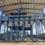
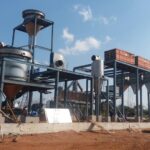
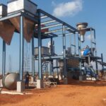
SALT PROCESSING PLANT – 25 TONS PER HOUR
Brief Process Description:-
The Raw Salt is fed into the concrete hopper made according to design
capacity. Raw salt (size up to 50mm) flow rate is regulated by gate valve which is
inserted at the bottom part of concrete hopper. So gate valve transfers the raw salt from
concrete hopper to inclined belt conveyor.
The inclined flat belt conveyor carries the raw salt up and drops it into the
wet mill. In inclined belt conveyors, plate magnets are inserted to collect iron particles
coming with raw salt. In the Wet mill, one more part of salt is turbulently encountered
with two parts of brine opening the salt particles to maximum surface area with a particle
size averaging 2000 microns. The crushed particles along with the brine are ejected into
the elutriation tank placed below wet mill.
The elutriation process entails a gradual pre wash of fluidized design with the
salt particles slowly descending against ascending brine current. The floating impurities
are carried over to the settling pond along with the brine overflow. The insoluble particles
are flushed out from the bottom of the tank at regular intervals. The washed salt is
carried over by a centrifugal slurry pump to the washing tank. The feed to the pump is at
a level above the conical bottom.
The washing tank is constructed similar to the elutriation tank except for an
agitator mounted within to ensure the particles to not settle due to the lower brine
velocity.
The brine pump has a semi open impeller of SS 304 construction running at
a high speed and always flooded. All pipes are of SS 304 Construction to withstand
pressure up to 3 kg/sqcm. Brine pump is placed at the settling pond and it supplies the
brine water to different equipment of plant to improve quality.
The over flow of the washing tank should now contain a minimum of clay content and a
small portion of calcium and magnesium impurities. Second slurry pump supplies salt
slurry from washing tank to static thickener.
The static Thickener is required to increase the solids ratio from 30% to at
least 70% in order to feed the pusher centrifuge with an optimum product enabling the
centrifuge to yield a much dryer final product.
Just before discharging into the pusher Centrifuge, a spray of fresh water will
assist removal of magnesium. At an average feed rate of 70% solids we may expect the
centrifuged products to have less than 4% moisture. The fuel consumption of the dryer
will reduce as much as we can reduce the moisture level of the centrifuged salt. The
pusher Centrifuge rotates a cylindrical basket about a horizontal axis. A pusher screen
ejects the centrifuged salt at a frequency measured as the number of stroke per minute
and amplitude denote as the stroke length. The power consumed and dryness achieved is
both directly proportional to the drier. Output salt of pusher centrifuge contains 4%
maximum of moisture.
After pusher centrifuge, moisturized salt is transferred to fbd feeder by screw
conveyor and in this screw conveyor, iodine solution is added whenever it is required to
manufacture iodized salt. FBD Feeder design such a way that it distributes the salt
quantity in fluidized bed dryer particular zone.
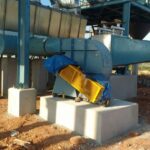
Fluidized bed dryer is operated by centrifugal blowers (cold air blower, hot air
blower and exhaust blower) and Cyclone. In FBD, air having the temperature of almost
220 degree C fluidizes the salt as a bed giving a time of five to ten minutes before
discharging. Hot air blower duct connected to heat exchanger, which gives hot air to FBD.
In heat exchanger, hot oil of 250°C is circulated operated by boiler unit. All blower
settings are such a way that create vacuum in FBD so salt particle movement will be
easy.
Exhaust blower sucks air with dust, created in fbd and this dust will be collected
in cyclone. Rotary airlock valve is attached at bottom of cyclone to collect fine dust
constantly. Due to these blowers, dry salt with small lump will go forward to bucket
elevator inlet and these small salt lump is removed by lump removal screen inserted
between dryer and bucket elevator. The salt exits the drier with moisture content of
0.05%. This material is of a highly free flow nature requiring silica to be added.
Discharge of the drier co-insides with the inlet of the Bucket Elevator. The
elevator carries the product salt up to a level where it is distributed by ducting into
circular vibrating screens. According to requirement, wire mesh is used in vibrating screen
like 850 micron, 900 micron, 1200 micron etc. Product salt is transferred by screw
conveyor and this product screw conveyor, anti caking agent silica is added to make final
product free flow type.
Over size of the screens discharge into the pin mill where tapered pins break
down the lumps while scrapers gently granulate the agglomerates and outlet product of
pin mill is transferred to dryer or bucket elevator.
Product screw conveyor carries final iodized salt from vibrating screen to packing
silos where it will be packed by FFS automatic machines in 500gms or 1kg according to
customer requirement. The iodized salt packets must be supplied from company by any
transportation best suited to the customers.
Provisions for Land, Water, Fuel & Power
SN | Content | Raw Salt | Quality of Finished |
1 | Nacl | 97% – 97.5% | 99.1% – 99.5% |
2 | Ca | 0.3% – 0.4% | 0.08% – 0.12% |
3 | Mg | 0.1% – 0.2% | 0.04%-0.07% |
4 | So4 | 0.8% – 1.2% | 0.15% – 0.3% |
5 | Insoluble | 0.2% – 0.3% | 0.05% – 0.10% |
6 | Moisture Content | 4% – 5% | 0.15% – 0.20% |
